Metric T-type synchronous belt gear tooth classification: T2.5, T5, T10, T20, AT5, AT10
Metric T-type synchronous pulley Raw materials: generally made of steel, aluminum alloy, cast iron, brass, etc. The inner hole has round hole, D-shaped hole, conical hole and other forms.
Metric T-type synchronous pulley surface treatment: natural oxidation, blackening, zinc plating, color zinc plating, high-frequency quenching and other treatment. Accuracy level depends on customer requirements.
1, the metric T-type synchronous belt produced by our factory is not only for the metric T-type synchronous belt of domestic equipment, but also can replace the imported T-type synchronous belt.
2, user customized metric T-type synchronous pulley, please provide pulley drawings (the drawing can not draw the tooth shape size of the pulley), our factory can also draw pulley drawings according to the specifications provided by the user, the inner hole of the pulley, the keyway, the width and other dimensions.
3, our factory metric T-type synchronous belt wheel can be processed according to user needs, and our factory can also develop drawings for users.
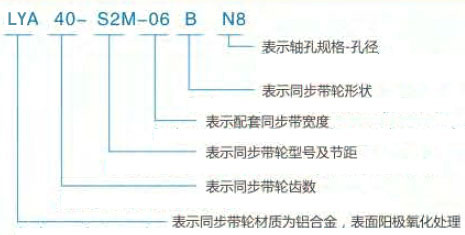
| Presentation method | Code | Material | Surface treatment |
|
LYA | Aluminum alloy | Natural anodizing |
| LYZ | Hard oxidation | ||
| LYH | Do not process | ||
| LYY | 45# steel | Blackening treatment | |
| LYD | Galvanizing | ||
| LYM | Do not process |
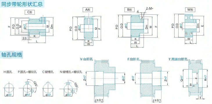
| Standard keyway size table (dH7: indicates inner hole size; bJS9: indicates the keyway width; t tolerance: keyway depth | |||||||||||||||||||||
| Model | dH7 | bJS9 | t tolerance | Model | dH7 | bJS9 | t tolerance | Model | dH7 | bJS9 | t tolerance | ||||||||||
| N8 | 8 | +0.015 0 |
3 | ±0.0125 | 1.4 | +0.1 0 |
N23 | 23 | +0.021 0 |
8 | ±0.018 | 3.3 | +0.2 0 |
N38 | 38 | +0.025 0 |
10 | 0.018 mm | 3.3 | +0.2 0 |
|
| N10 | 10 | N24 | 24 | N39 | 39 | 12 | ±0.0215 | ||||||||||||||
| NK10 | 10 | +0.018 0 |
4 | ±0.015 | 1.8 | N25 | 25 | N40 | 40 | ||||||||||||
| N11 | 11 | N26 | 26 | N41 | 41 | ||||||||||||||||
| N12 | 12 | 2.3 | N27 | 27 | N42 | 42 | |||||||||||||||
| N13 | 13 | N28 | 28 | N43 | 43 | ||||||||||||||||
| N14 | 14 | 5 | N29 | 29 | N44 | 44 | |||||||||||||||
| N15 | 15 | N30 | 30 | N45 | 45 | 14 | 3.8 | ||||||||||||||
| N16 | 16 | N31 | 31 | N46 | 46 | ||||||||||||||||
| N17 | 17 | N32 | 32 | +0.025 0 |
10 | N47 | 47 | ||||||||||||||
| N18 | 18 | 6 | 2.8 | N33 | 33 | N48 | 48 | ||||||||||||||
| N19 | 19 | +0.021 0 |
N34 | 34 | N49 | 49 | |||||||||||||||
| N20 | 20 | N35 | 35 | N50 | 50 | ||||||||||||||||
| N21 | 21 | N36 | 35 | ||||||||||||||||||
| N22 | 22 | N37 | 37 | ||||||||||||||||||
| Note: when the shaft hole is 10, the keyway width is 4.0MM, and the keyway depth is 1.8MM, the shaft hole is indicated by NK10 | |||||||||||||||||||||
| Model | Pitch Pb | Tooth profile Angle 2y° | Top width br | Tooth height hg | Root radius rb | Tip radius rt |
| T2.5 | 2.50 | 50 | 1.83 | 1.00 | 0.20 | 0.30 |
| T5 | 5.00 | 3.32 | 1.95 | 0.40 | 0.60 | |
| T10 | 10.00 | 6.57 | 3.40 | 0.60 | 0.80 | |
| T20 | 20.00 | 12.6 | 6.00 | 0.80 | 1.20 |
| Model | Pitch Pb | Tooth profile Angle 2y° | Slot width S | Tooth height hg | Root radius rr | Tip radius ra |
| AT3 | 3.00 | 50 | 1.50 | 1.00 | 0.20 | 0.30 |
| AT5 | 5.00 | 2.70 | 1.10 | 0.40 | 0.70 | |
| AT10 | 10.00 | 5.40 | 2.35 | 0.50 | 1.20 | |
| AT20 | 20.00 | 10.00 | 5.00 | 1.75 | 2.50 |


